| Company News | | | Industry News | | |
Original title: Application of energy-saving technology for step-by-step heating furnace
In the metallurgical industry, the steel rolling heating furnace is one of the main energy consuming equipment for rolling production lines. It is of great significance to make rational use of energy-saving technology of heating furnace, improve fuel utilization rate, reduce energy consumption, reduce oxidation burning loss of billet and improve heating quality.
The heating furnace for the section steel workshop of Laigang Bar Plant, built by Beijing Shenwu, was put into use in June 2009, with a designed heating capacity of 120t/h. The heating furnace is a side entry and side exit walking beam continuous heating furnace, with a billet of [(150 × 150)mm~(160 × 160)mm] × (9000-10000) mm, using high coke mixed gas as fuel and adopting multiple energy-saving technologies to achieve energy-saving goals.
1. Energy saving technology of step-by-step heating furnace
1.1 Air regenerative combustion technology
The heating furnace adopts the integrated combustion technology of air heat storage and gas heat exchange. The gas is preheated by the Fried Dough Twists plug-in tube heat exchanger. The gas preheating temperature is 350 ℃. The air uses the regenerative combustion technology to preheat the combustion supporting air at 20 ℃ to a high temperature of 850-900, reaching the limit recovery of flue gas waste heat, improving the physical heat of combustion medium, thereby reducing fuel consumption and improving the thermal efficiency of the heating furnace by 30%. It is a new technology of energy conservation and environmental protection.
By using regenerative combustion technology, the flame flow inside the furnace is significantly different from that of traditional heating furnaces. The exhaust gas flows horizontally, and the burners work in pairs. The burners are arranged on both sides of the heating furnace, with one side of the burner working and the other side of the burner discharging smoke and storing heat. The flame emitted by one side of the burner is attracted by the opposite side of the burner, which is equivalent to lengthening the flame length. Therefore, the temperature in the width direction of the heating furnace is more uniform than that of traditional heating furnaces.
After the regenerative combustion technology is adopted, the heating temperature is uniform, the billet heating quality is good, and no furnace sticking accident occurs. After the gas and air heat are stored, the low oxygen diffusion combustion technology is adopted to form a new flame type that is different from the traditional flame. The combustion atmosphere in the furnace is good, the billet temperature rises faster, and the billet oxidation burning loss can be reduced by 0.3% - 0.5%.
1.2 Combustion equipment and combustion method
The heating furnace in the steel workshop of the bar mill adopts an air single heat storage upper and lower combined burner, with a total of 52 single heat storage burners and single heat storage combined burners. Each section of the burner can be adjusted separately, and the regenerative burners work in pairs. The two alternate combustion and smoke exhaust working states, and the heat storage body in the burner changes the heat release and absorption states accordingly. The paired burners are located on the A and B sides of the furnace. When the A side burner burns, The air is heated by passing through a heat storage body that has accumulated heat. At the same time, the B side burner exhausts smoke, and the heat of the flue gas is absorbed by the heat storage body for heat storage. Through the medium of the heat storage body, the residual heat of the discharged flue gas is converted into physical heat of the air, which is recycled and utilized, as shown in Figure 1.
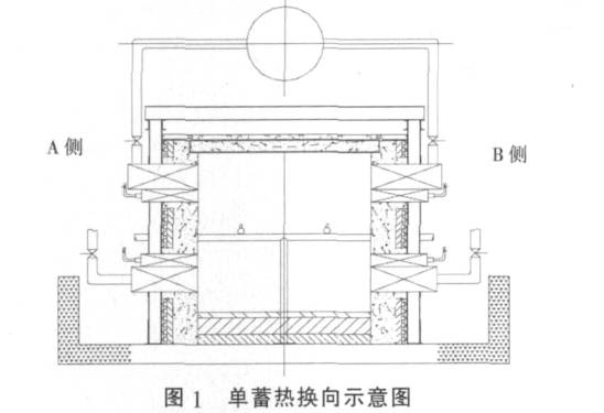
The air nozzle and gas nozzle of the regenerative burner are a combination of upper and lower parts. When the burner is installed in the upper part of the furnace, the air nozzle is above and the gas nozzle is below, and the air and gas flow are mixed diagonally. When the burner is installed in the lower part of the furnace, the opposite is true. The gas nozzle is above and the air nozzle is below, which means that the gas flow is close to the upper and lower surfaces of the billet. There is a brief process of mixed combustion of air and gas, during which the atmosphere in contact with the surface of the billet is reducing or slightly reducing. The billet oxidizes slowly and the oxidation loss decreases by 0.45%. This is a clear characteristic of the combined regenerative burner. The structure of the upper and lower combined burner is shown in Figure 2.
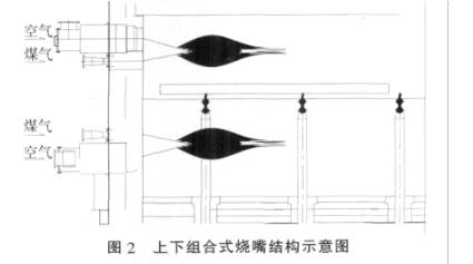
By using a regenerative burner, the exhaust temperature of the flue gas can be reduced to below 150 ℃, the air can be preheated to above 850 ℃, the heat recovery rate can reach over 85%, and the temperature efficiency can reach over 90%. This not only saves a lot of energy, but also significantly reduces the amount of smoke emitted into the atmosphere, with good environmental protection effects.
1.3 High calorific value gas heat exchange combustion technology
Due to the use of mixed gas as fuel in the heating furnace of the bar mill, the calorific value of the fuel is 10450kJ/m ³ Above all, the fuel has a high calorific value. If the gas is also used as a regenerative type, the temperature of both air and gas is at 10000 ℃, and the theoretical combustion temperature of the combustion products is very high. In previous engineering projects, using regenerative combustion for high calorific value gas has unstable operation and is not suitable for the low-temperature furnace requirements of high-quality steel. According to the actual situation, in order to better reduce fuel consumption and meet the requirements of low-temperature furnace feeding and slow heating of Youte Steel, conventional preheating is used for gas, with a preheating temperature of 350 ℃.
1.4 Application of variable frequency speed regulation technology
Variable frequency speed regulation technology changes the speed of the motor by changing the frequency of the stator power supply of the motor, and correspondingly changes the speed and working condition of the fan to adapt to the changes in the operation of the heating furnace. The energy-saving effect of using variable frequency speed regulation technology is obvious. Due to the fact that the shaft power P is proportional to the cube of the speed n, i.e. the power decreases to the third power of the speed n. After the speed decreases, the operation of the fan has a significant effect on reducing consumption. The blower and induced draft fan adopt variable frequency speed regulation technology, controlling the motor speed to be around 65% of the rated value. The motor speed can be adjusted to meet the conditions of air supply and smoke exhaust in the heating furnace, with a power saving rate of up to 30% and significant economic benefits.
1.5 Furnace Wall Structure and Materials
The heat loss of the furnace wall includes two items: heat dissipation loss and heat storage loss. The heat loss of the furnace wall is calculated as follows:
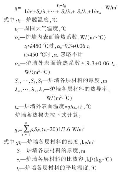
Through the calculation and selection of the heat loss of the furnace wall mentioned above, the heating furnace in the bar factory adopts high-performance refractory castable for overall casting of the furnace wall, and adopts a composite insulation layer structure to improve the furnace insulation. The composite furnace wall is divided into four layers, and the low cement casting material in the working layer has good high-temperature resistance, especially for the heating section furnace wall, which greatly improves the overall service life of the furnace lining. On the one hand, the lightweight bricks in the secondary working layer have good high-temperature insulation performance, and on the other hand, they play a role in anchoring the brick bracket, avoiding the cantilever force of the anchoring bricks during pouring material vibration. The outer refractory fiber board and refractory fiber blanket products have outstanding heat insulation effect. Due to the small specific heat capacity and low thermal conductivity of the materials, there is little heat storage in the furnace lining, which promotes the rapid temperature rise of the furnace and improves the combustion efficiency. The surface temperature of the furnace body is shown in Table 1.

1.6 Stable furnace pressure
Controlling the pressure inside the furnace is not only related to fuel conservation, but can also enhance the circulation of furnace gas and achieve uniform furnace temperature by controlling the pressure distribution inside the furnace. When the pressure inside the furnace is too high, high-temperature flue gas will escape outside the furnace, causing heat loss. When the pressure inside the furnace is too low, cold air is sucked in at the furnace mouth and loose areas, resulting in an increase in heat loss carried away by the flue gas leaving the furnace. The relationship between the pressure inside the furnace and the heat loss of the inhaled air and the escaped flue gas is shown in Figure 3.
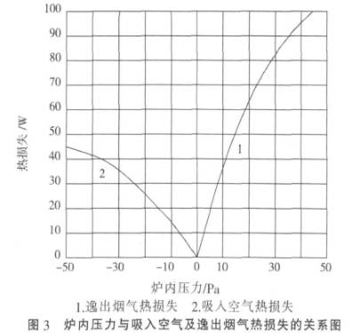
If the pressure inside the furnace is too high or too low, it will lead to an increase in heat loss. In order to reduce the above heat loss, control technology is adopted to adjust the opening of the flue gate in a timely manner to maintain the normal pressure value inside the furnace.
1.7 Application of Vaporization Cooling Technology
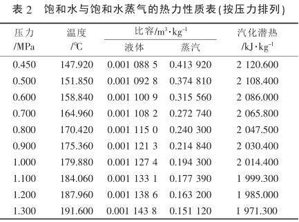
The step-by-step heating furnace adopts forced vaporization cooling technology. The higher the pressure, the greater the latent heat of vaporization, and the more heat taken away by saturated steam of equal quality, as shown in Table 2. It can save energy, electricity, and water. It can effectively utilize the recovered heat, reduce black marks on the heated steel billets, extend the service life of the cooling components in the furnace, and make the operation of the heating furnace safer and more reliable.
The forced vaporization cooling system of a walking beam heating furnace is composed of equipment such as a soft water treatment system, a water supply pump, a steam drum, a circulating pump, and flexible components. The cooling process flow is as follows: soft water - soft water tank - soft water pump - deaerator - feedwater pump - steam drum - downcomer - thermal circulation pump - distribution header - (fixed beam) - inlet stepper device - movable beam - outlet stepper device - rising pipe - steam drum - steam separated and sent to the plant network management.
When circulating water enters each fixed beam and movable beam, automatic control is used to adjust the water volume, so that the water volume is reasonably distributed according to the size of each group's heat load. After the steam water mixture returns to the steam drum, it undergoes steam water separation. The steam is stored in the upper part of the steam drum and delivered to the user according to the required parameters for external supply. The water is stored in the lower part of the steam drum and participates in recycling together with the make-up water.
At the contact between the heated billet and the water cooling beam, due to the use of forced vaporization cooling technology, the cooling temperature of the water beam is higher than that of the traditional water cooling, improving the heating quality of the billet, reducing the factors that reduce the yield due to "black printing", and increasing the yield by 0.5%. Increase the circulating water circulation rate and reduce equipment installation space.
2. Technical level and economic effect
After 5 months of production and operation, the heating furnace of the bar factory has reached the designed production capacity, and all economic and technical indicators have reached the national advanced level. According to the analysis of production operation statistics, the gas consumption of the walking beam heating furnace is 1.1GJ/t steel, the comprehensive energy consumption is reduced by 5 kg/t steel, the yield rate is increased by 0.5%, and emissions are significantly reduced. At the same time, the service life of the cooling components of the walking beam heating furnace is extended, the downtime for maintenance is reduced, and the operating rate is improved.
3. Conclusion
In the design process of the walking beam heating furnace in the section steel workshop of the bar mill, multiple energy-saving technologies have been adopted, especially the comprehensive application technology of air single storage and gas preheating, and the forced vaporization cooling technology have been successfully applied to the heating furnace of the wire production line. Production practice has proven that the energy-saving and emission reduction effect is obvious, and it is worth promoting.
Phone:13801428399
Add:xinqiao town industrial park, jingjiang city, jiangsu province
Mail:13801428399@126.com
Home:www.jsdfct.cn

Official account

Mobile station